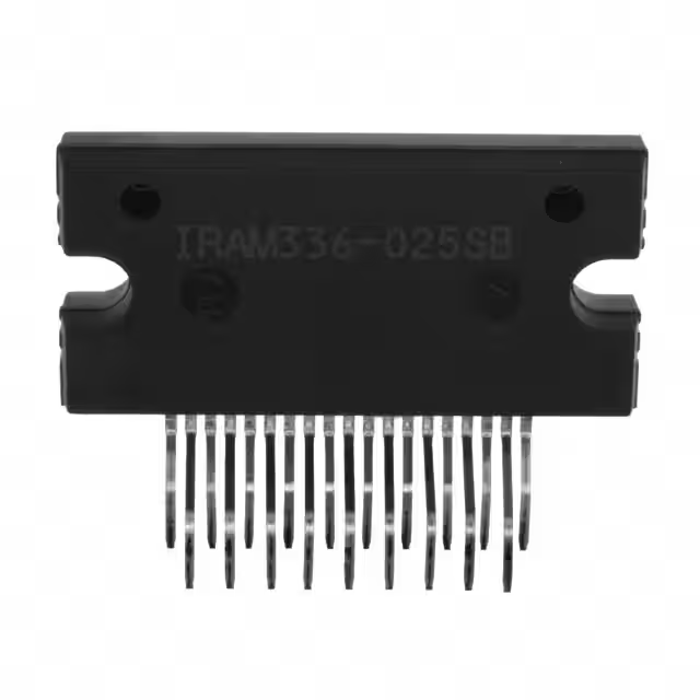
IRAM336-025SB is a multi-chip hybrid IC for low power electrical motor control applications such as fans, pumps and refrigerator compressors. A compact Single in line (SIP-S) package minimizes PCB space. Several built-in protection features such as temperature feedback, shot prevention, undervoltage locking and shutdown input make this a very powerful solution.
Internal electrical schematic diagram

The combination of high-efficiency high-voltage MosFETs and industry benchmark three-phase HVIC drivers (3.3V/5V input compatible) and heat-enhanced packaging makes it a highly competitive solution. A bootstrap power supply for the high-side driver can be generated using an internal bootstrap diode, eliminating the need for an isolated power supply. This feature reduces the number of components, board space, and system costs.
Typical Application Circuit

Application circuit recommendation
1.)Electrolytic bus capacitors should be mounted as close to the module bus terminals as possible to reduce ringing and EMI problems. Additional high frequency ceramic capacitor mounted close to the module pins will further improve performance.
2.) In order to provide good decoupling between VCC-VSS and Vb-Vs terminals, the capacitors shown connected between these terminals should be located very close to the module pins. Additional high frequency capacitors, typically 0.1µF, are strongly recommended.
3.)The value of the bootstrap capacitor depends on the switching frequency. They should make a choice According to IR design tip DN 98-2a or Application instructions AN-1044 or figure below

4.)8ms FAULT Automatic reset PWM generators must be disabled during the automatic reset time (TFLT-CLR) to ensure that the system is shut down and overcurrent conditions must be cleared before resuming operation.

5.)The enclosure of the module is connected to the negative DC bus and is not isolated. You are advised to install insulation materials between the chassis and the heat sink to prevent electric shock.
Features
● Motor Power up to 250W / 85~253 Vac.
● Integrated Gate Drivers and Bootstrap Diodes.
● Over-the-current Shut-Down function.
● Under-voltage lockout for all switches.
● Matched propagation delay for all channels.
● Schmitt-triggered input logic.
● Cross-conduction prevention logic.
● Lower di/dt gate driver for better noise immunity.