IR2153 Introduction
The IR2153 is an enhanced version of the widely-used IR2155 and IR2151 gate driver ICs, integrating a high-voltage half-bridge gate driver and a front-end oscillator, similar to the CMOS 555 timer. This improved design offers greater functionality and ease of use compared to its predecessors.
Notably, the IR2153 features a shutdown capability through the CT pin, allowing both gate driver outputs to be disabled via a low-voltage control signal. Additionally, it offers stable gate driver output pulse widths and improved noise immunity, achieved through lower di/dt and a 1V undervoltage lockout hysteresis, along with enhanced latch immunity and comprehensive ESD protection.
IR2153 Pinout

VCC: Supply voltage input pin that powers the internal circuitry.
RT: Timing resistor pin is used to set the oscillator frequency.
CT: Timing capacitor pin used along with RT to define the switching frequency.
COM: Common ground pin.
LO: Low-side gate driver output pin for controlling the low-side MOSFET.
VS: High-side driver return pin, connected to the source of the high-side MOSFET.
HO: High-side gate driver output pin for controlling the high-side MOSFET.
VB: High-side gate driver supply voltage pin.
IR2153 Symbol

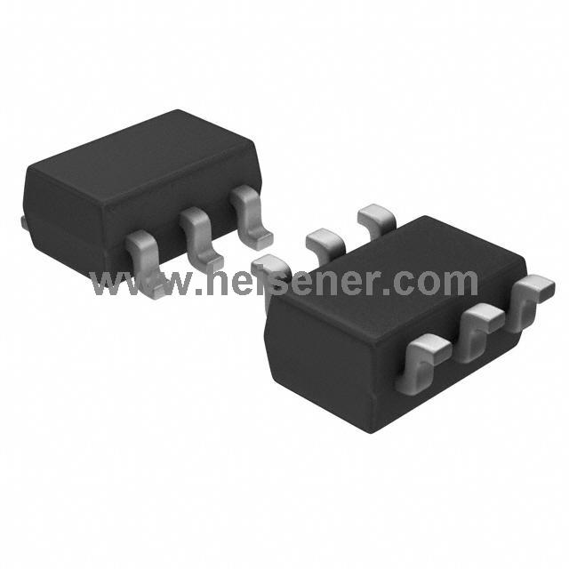
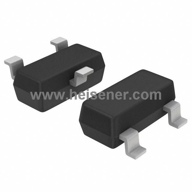
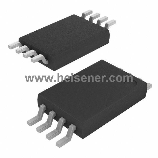
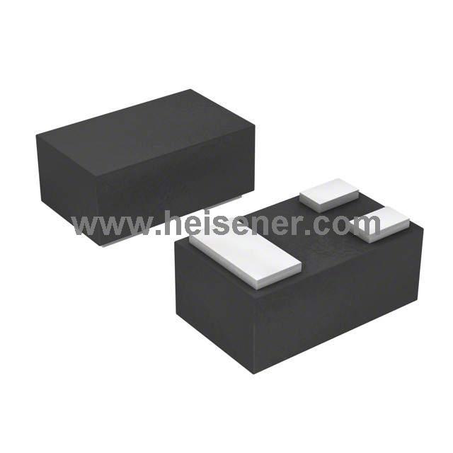
IR2153 Footprint

IR2153 3D Model

IR2153 Typical Connection

IR2153 Functional Block Diagram

IR2153 Specification
| Specification | Value |
| Supply Voltage (VCC) | 10V - 15.6V |
| Quiescent Current (VCC) | 180 µA |
| Gate Driver Voltage | 600V |
| Output Source Current | 290 mA |
| Output Sink Current | 600 mA |
| Undervoltage Lockout | 9.4V (rising), 8.4V (falling) |
| Oscillator Frequency | Adjustable (determined by RT and CT) |
| Operating Temperature | -40°C ~ 150°C |
| Deadtime | 1.2 µs (typical) |
| High-Side Voltage (VB-VS) | 10V to 20V |
| ESD Protection | Yes (on all pins) |
IR2153 Features
Integrated 600V half-bridge gate driver
15.6V zener clamp on Vcc
True micropower start up
Tighter initial deadtime control
Low temperature coefficient deadtime
Shutdown feature (1/6th Vcc) on CT pin
Increased undervoltage lockout Hysteresis (1V)
Lower power level-shifting circuit
Constant LO, HO pulse widths at startup
Lower di/dt gate driver for better noise immunity
Low side output in phase with RT
Internal 50nsec (typ.) bootstrap diode (IR2153D)
Excellent latch immunity on all inputs and outputs
ESD protection on all leads
Also available LEAD-FREE
IR2153 Applications
Half-Bridge and Full-Bridge Drivers
DC-DC Converters
Inverters
Motor Control
Power Amplifiers
Lighting Control
Inductive Heating
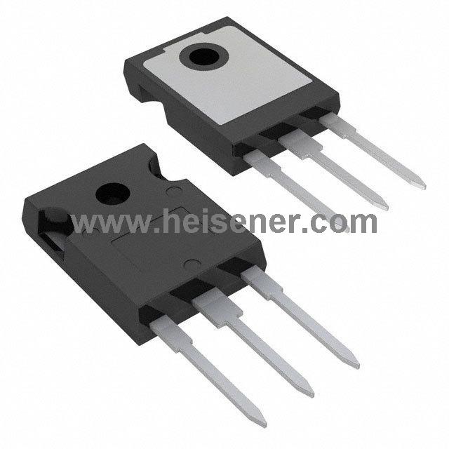
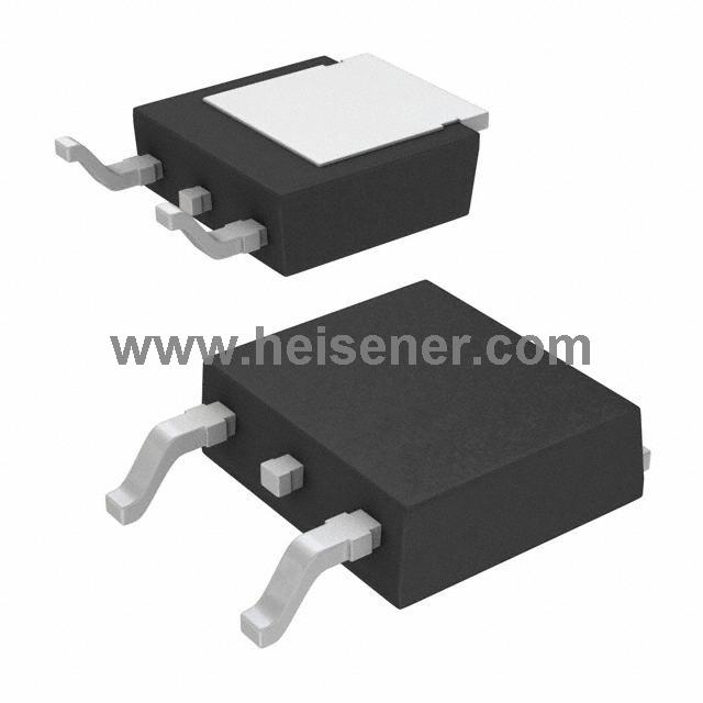
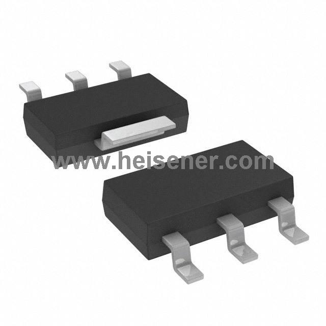
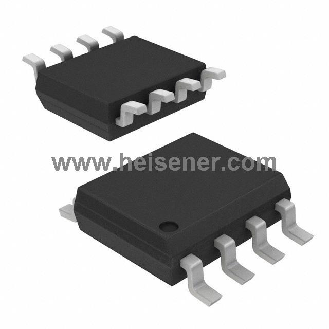
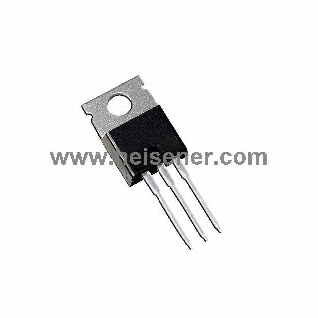
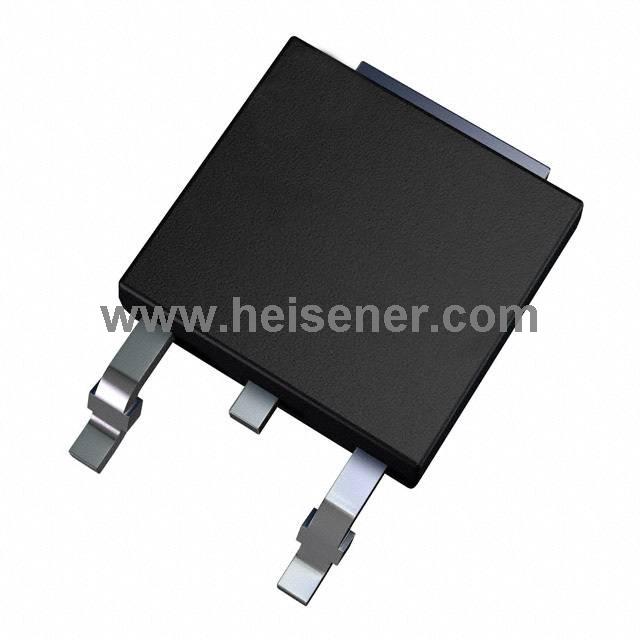
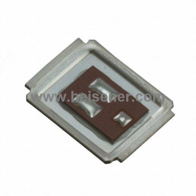
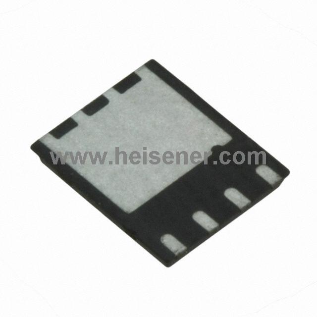
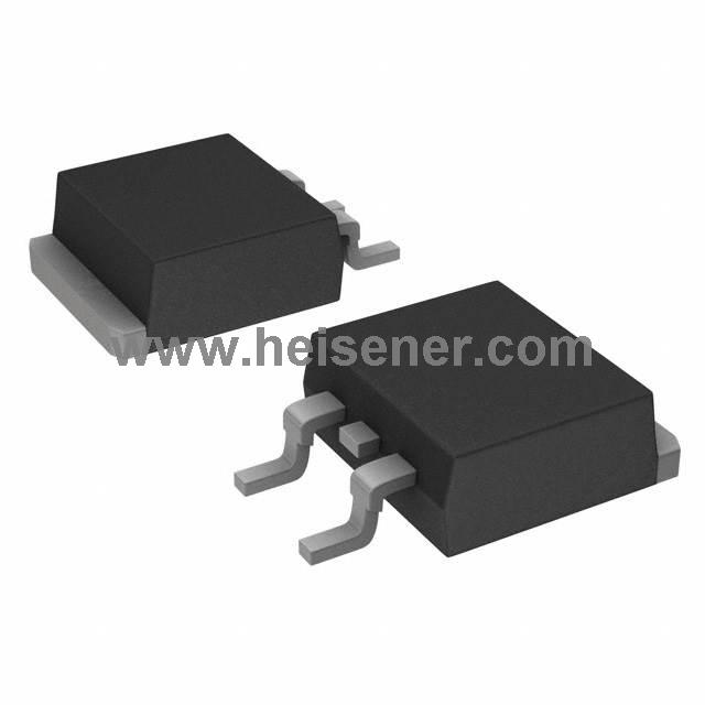
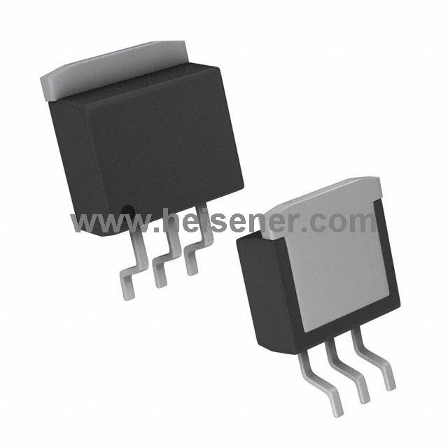
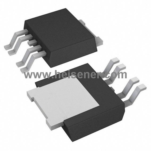
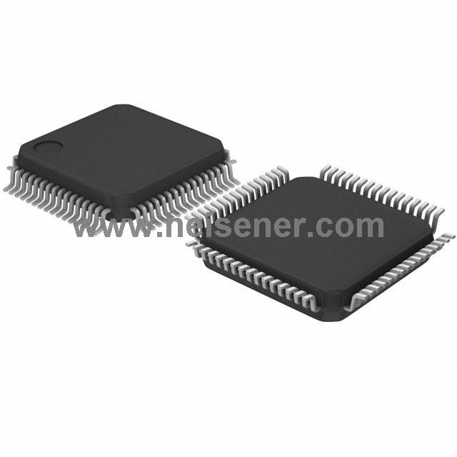
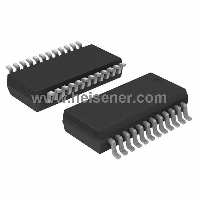
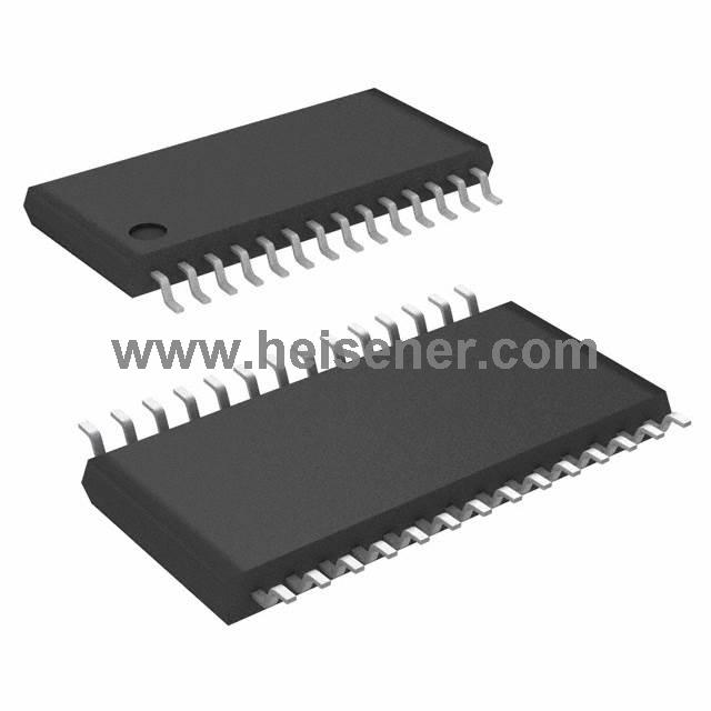
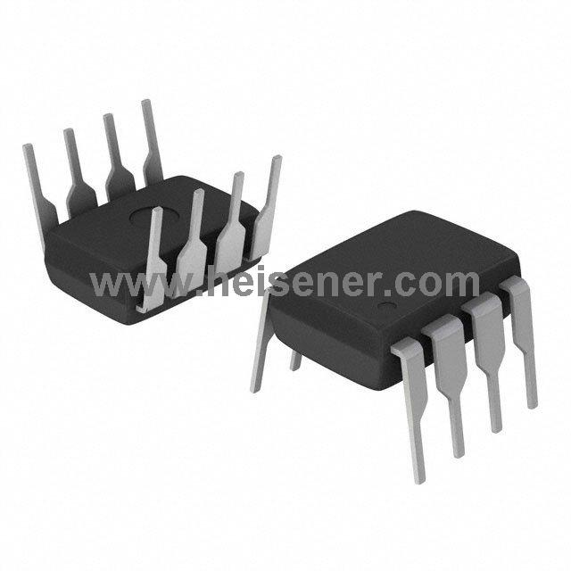
IR2153 Package

How to Use IR2153?
First, connect the power supply to the VCC pin of the IR2153. Simultaneously, connect the COM pin to ground. Next, select appropriate resistor (RT) and capacitor (CT) values, and connect them to the corresponding pins. These components will set the operating frequency of the IR2153. You can determine the desired oscillation frequency using the formula f=1.1/(RT×CT).
Then, connect the LO pin and HO pin to the required power switching devices, such as MOSFETs or IGBTs. After powering on the circuit, control the CT pin with a low voltage control signal to enable or disable the driver outputs. Use an oscilloscope to measure the output waveforms at the LO and HO pins to ensure they meet the expected frequency and duty cycle requirements.
FAQs
What is IR2153?
The IR2153 is a high-voltage half-bridge gate driver IC designed for driving power MOSFETs and IGBTs in applications such as motor control, power inverters, and switching power supplies. It features an integrated oscillator for frequency generation and improved noise immunity.
What type of power devices can be driven by IR2153?
The IR2153 can drive various power switching devices, including MOSFETs and IGBTs, making it suitable for a wide range of applications.
How can I enable or disable the gate driver outputs?
The gate driver outputs can be enabled or disabled by applying a low voltage control signal to the CT pin. When the CT pin is low, both gate driver outputs are turned off.
Where can I find the datasheet for IR2153?
The datasheet for the IR2153 can be found on the manufacturer's website or through electronic component distributors, providing detailed specifications, application notes, and circuit examples.