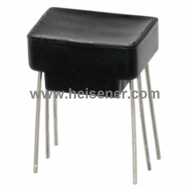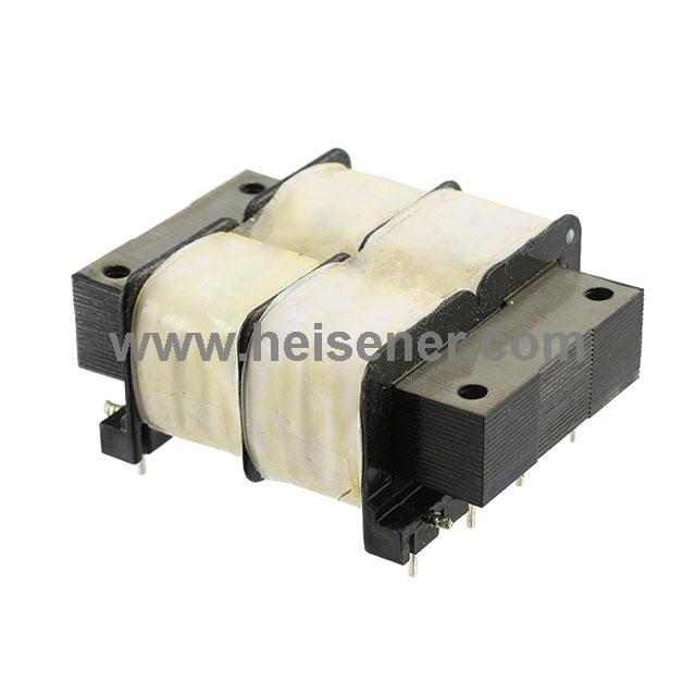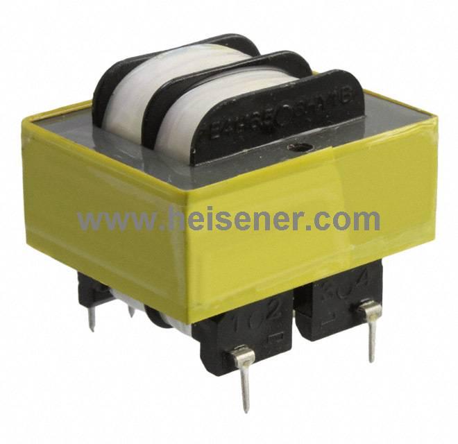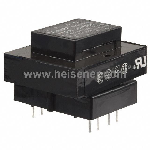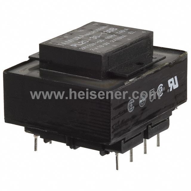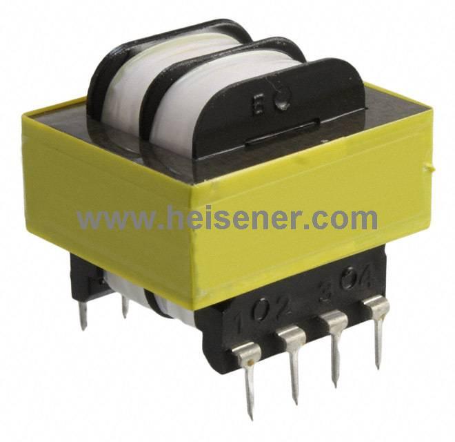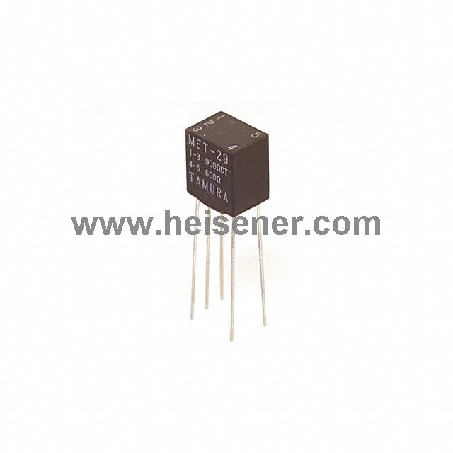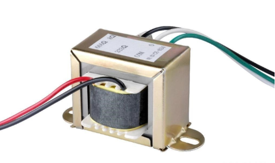
An audio transformer is a transformer that works in the audio frequency range. Its typical operating range is 20Hz to 20kHz. It transfers AC audio signals between the primary and secondary windings through electromagnetic induction. This allows impedance matching, voltage conversion, and electrical isolation.
Audio transformers can be step-up or step-down types. They can also use a 1:1 turns ratio as an isolation transformer. The main design focus is impedance matching and frequency response. To ensure good sound quality, audio transformers use high-permeability magnetic cores and tightly coupled windings. They are widely used in radio communication, broadcasting, audio amplifiers, and automatic control systems.
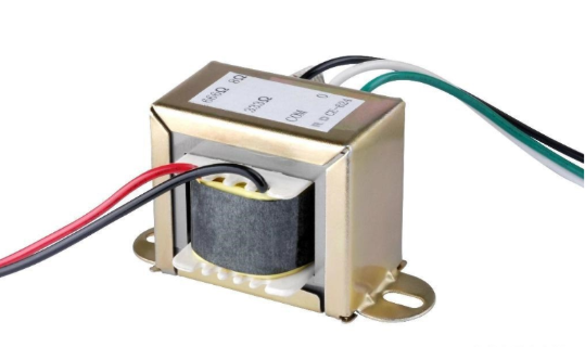
Structurally, an audio transformer is made of a primary winding and a secondary winding wound on a high-permeability soft magnetic core. There is no direct electrical connection between the input and the output, so it can effectively isolate DC components and reduce ground loop noise. When an AC audio signal is applied to the primary winding, magnetic coupling in the core induces a corresponding AC signal in the secondary winding. The output voltage and current depend on the turns ratio between the two windings.
Audio transformers also use impedance balancing. This is very useful when matching amplifiers and loads with different input or output impedances, such as speakers, to achieve maximum power transfer.
Today, speaker impedance usually ranges from 4 to 16 ohms, with common values of 4 Ω, 8 Ω, and 16 Ω. In comparison, transistor or solid-state amplifiers often have output impedances of 200 to 300 ohms. In older designs, such as vintage valve or tube amplifiers, the output voltage can reach 300 V with an impedance of around 3 kΩ. In these cases, an impedance matching transformer is needed. It converts high impedance to low impedance and adjusts voltage and current to levels suitable for directly driving speakers.
A transformer can have multiple windings on both the primary and secondary sides. The ratio between the number of turns on the primary winding (Np) and the secondary winding (Ns) is called the turns ratio. This ratio also defines the voltage ratio, since voltage is proportional to the number of turns. The relationship is shown below:
Np / Ns = Vp / Vs
Impedance is the critical parameter in an impedance-matching transformer. In audio or power transfer applications, the transformer's efficiency and performance depend on the proper matching between primary and secondary impedances.
For an impedance-matching transformer, the relationship between primary and secondary impedances can be determined using the turns ratio or the voltage ratio.
In practice, the impedance ratio is calculated by squaring the transformer's turns ratio or voltage ratio. This principle underlies the impedance transformation capability of audio and power transformers.
Impedance Ratio Formulas

Or
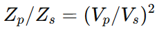
Notation
- Zp: Primary impedance
- Zs: Secondary impedance
- Np / Ns: Primary-to-secondary turns ratio
- Vp / Vs: Primary-to-secondary voltage ratio
Since the impedance ratio equals the square of the turns ratio or voltage ratio, a transformer with a 4:1 turns (or voltage) ratio provides a 16:1 impedance ratio. This characteristic enables impedance-matching transformers to achieve efficient and stable power transfer between high-impedance and low-impedance circuits.
Audio transformers can function like power transformers for voltage conversion, or they can be used for audio signal coupling. The main functions of audio transformers are as follows:
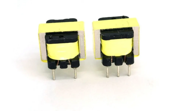
Output Transformer:
Output transformers are used in audio playback and amplification devices. They primarily provide impedance matching in the circuit.
Input Transformer:
Input transformers work when audio signals enter a circuit. Their main function is also impedance matching.
Interstage Transformer:
Common interstage transformers help to harmonize the operating stages within an amplifier, ensuring smooth signal transfer between amplifier sections.
Line Transformer:
Line transformers are often used in wired broadcasting systems. In these systems, multiple high-power amplifiers and long transmission lines can cause audio distortion. Line transformers help maintain signal integrity over long distances.
Audio transformers are similar to regular transformers in principle, but they differ significantly in design and application to meet specific operating environments and performance requirements. Audio transformers are specially designed for transmitting audio signals and can operate stably within the 20 Hz to 20 kHz frequency range, while regular transformers are generally used for power transmission or low-frequency applications, with a broader operating frequency range.
In terms of frequency response, audio transformers are designed to provide a flat response across the entire audio range, ensuring more accurate signal transmission. Regular transformers may not be optimized for frequency response, as their main focus is often on power transfer efficiency and electrical isolation.
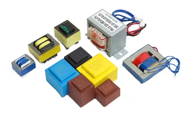
Audio transformers usually feature multiple windings, including primary and secondary coils, to achieve signal isolation and coupling, while also paying attention to impedance matching. Regular transformers may have a single winding and focus more on power matching and electrical safety.
Additionally, because audio transformers operate at higher frequencies, their size and weight are generally designed to be compact and lightweight to suit audio equipment and other audio applications. In contrast, regular transformers, designed for high-power transmission, are usually larger and heavier.
Winding a high-performance audio transformer requires balancing low-frequency and high-frequency performance. To reduce leakage inductance and improve low-frequency response, the primary coil should have more turns. To enhance high-frequency performance, the inter-winding capacitance should be minimized. Turns, leakage inductance, and inter-winding capacitance are interrelated, so choosing the right core material is very important. High-silicon steel with high magnetic flux density is recommended, and a shell-type structure can help increase inductance and reduce leakage inductance with a limited number of turns.
At the low-frequency end, core saturation can affect performance. Adding a gap spacer between the cores can prevent saturation, but it also increases leakage inductance. Making an audio transformer requires careful trade-offs between core material, gap design, and winding turns, which usually relies on experience.
For the winding structure, to avoid DC magnetization caused by push-pull tube amplifier imbalance, the upper and lower tube windings must have matched inductance and DC resistance. Using layered and edge-wound techniques can reduce inter-winding capacitance and improve frequency response. The more layers and the finer the winding, the better the output signal performance.